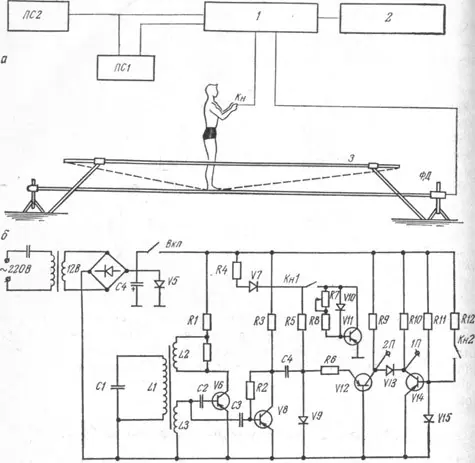
It turns out that there is a special simulator for practicing the key movements of track and field athletes on such a well-known apparatus as trampoline. The device described below helps athletes hone their trampoline jumps, improving movement technique, spatial coordination and self-confidence. Let's consider its structure and principle of operation.
Content- Trainer for correction in trampoline jumping.
- Schematic diagram of the training device.
- Operating principle of the device for athletes.
Trainer for correction in trampoline jumping.
The device is designed for particularly accurate measurement of the flight duration while jumping on a trampoline and determining the accuracy of athletes’ subjective perception of the entire flight and its individual parts.
The simulator (see figure) serves to measure the time during which the photodiode is illuminated, which occurs when the acrobat, performing an exercise on trampoline 3 (Figure a), is in an unsupported position.
Schematic diagram of the training device.
The device consists of a sinusoidal voltage generator 2 with a frequency of 10 kHz with parametric frequency stabilization (on triode V6), a voltage amplifier V8, a sinusoidal voltage converter into square pulses of positive polarity (on a tunnel diode V9) and a square pulse amplifier V12. The device has two separate outputs (1P and 2P) and an electronic switch for output 1P (V14, VI5). The device is powered from an alternating current network with a standard voltage of 220 V through a rectifier with ferroresonant voltage stabilization (Fig. 6). Control circuit 1 is supplied with signals from the Kn button and the PD photodiode.
Operating principle of the device for athletes.
When the power is turned on, the generator starts working, the alternating signal from the coil L through the capacitor SZ goes to the amplifier V8 and through the capacitor C4 goes to the tunnel diode V9. Through the chain R4, V7, R5, with the photodiode V10 darkened, a negative voltage is applied to this tunnel diode, and it shorts the incoming signal to ground without passing it to the conversion circuit. When the photodiode is illuminated, its resistance decreases sharply, and through the opened triode V11, the supply circuit of the tunnel diode V9 is shunted. As a result, the negative voltage on V9 drops and, under the influence of sinusoidal voltage, rectangular pulses are formed. These pulses, amplified by triode V12, enter the input of the 2P converting device and, through the separating diode V13, to the input of the 1P converting device. Both counting devices count pulses until the subject, at the moment perceived by him as given, presses the button of the microswitch Kn2. In this case, a larger negative voltage is supplied to the tunnel diode V15, which opens the triode V1, and it supplies signals to the ground that go to the first converting device PS1. Then the counting of pulses by this device stops. The second counting device PS2 continues counting pulses until the photodiode V10 is darkened again. To return the circuit to its original state, you need to remove the power from the switch.
In our next articles in this section, we will continue to introduce you to training devices from the World of Modern Sports. And if you are interested in fitness and bodybuilding equipment, then read this thread on our website. There is a lot of useful information here, both for young bodybuilders, and for experienced bodybuilders. And the range of topics covered will satisfy even the most demanding reader: all the nuances of training, aspects of recovery, nutritional recommendations, issues of figure correction and much, much, much more...
Post Views: 98


