The complex simulator studied in this review is designed to study the technique of athletics exercises and obtain urgent information about the kinematic parameters of the athlete’s movements. It is also used in the educational and training process of track and field athletes (race walking, running, jumping and throwing).
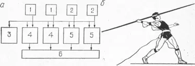
The complex simulator (Fig. 1) consists of three blocks - sensing, amplifying and recording. The sensing unit is equipped with contact insoles and strain gauge acceleration sensors, the amplifying unit is equipped with strain gauge amplifiers made using integrated circuits, and the recording unit is equipped with a recorder.
In Fig. 1, and a block diagram of the complex is shown: 1 - contact insoles; 2 — acceleration sensors; 3 - power supply; 4 — insole bridges; 5 — strain gauge amplifiers; 6 - recorder. In Fig. 1, b shows the working hours of the research.
The peculiarity of this complex simulator is its simplicity and portability. Thus, the entire amplifying part and power supplies are located on the inner lid of a wooden suitcase measuring 50X30X20 cm, and the suitcase itself is used for storing and transporting sensors and wired communications. All this allows the simulator to be widely used directly at the stadium when conducting educational training sessions.
Electronic sound leader.
The device is designed for programming the frequency of movements in cyclic sports in the range from 1...2 to 10 Hz, setting the rest interval of 10 and 60 s and assessing endurance (author A.D. Skripko).
The sound leader circuit (Fig. 2) consists of a sound generator VI, V2, which is turned on and off automatically using the second generator V3, V4, which is a clock generator. Both generators are assembled using a multivibrator circuit. The frequency of the sound generator is 2 kHz, and the clock generator is varied in the range [1 – 10] Hz by adjusting the resistance of the variable resistor.
The time interval of the training task or rest pause is set by a capacitive time relay assembled on V5, V6, relay RES64B. When the time relay is turned on, the capacitance is discharged and the contacts of the RES64B relay turn off the sound generator. The telephone used is a small-sized telephone TM-2M or a small-sized speaker connected through an output transformer. The circuit is powered by a voltage of 9 V from a 7D-01 battery or a regular battery. The circuit does not require special selection of transistors and can be assembled using six transistors.
The device is small in size and can be used in cyclic sports - rowing, cycling, cross-country skiing.
Post Views: 168


