In our previous articles we have already talked about training equipment for modern cyclists. As part of our section: “special sports devices and educational devices” we continue to study all kinds of devices for all lovers of pedals and steering wheels. And today you will get acquainted with another such interesting development, and also learn how to assemble a mechanical bicycle speedometer with your own hands.
Trainer for cyclists.
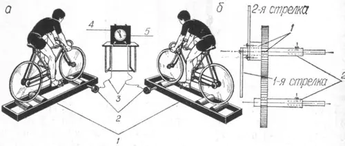
The machine is designed to improve the tactical actions of cyclists. This simulator allows racers to monitor not only their own work, but also the work of their opponents by moving the arrows on the screen.
The device (Fig. 1,a) consists of two bicycle machines 1, two gearboxes 2, cables 3 and a screen 4 with coaxially mounted arrows 5. Each gearbox represents a system consisting of two worm gears.
The gearbox is mounted on the bike frame at a distance of 25...30 cm from the front roller. A block (made of plastic or textolite) is mounted on the first worm of the gearbox, the circumference of which is equal to the circumference of the roller. The block with the rollers is connected by a rubber pulley. A flexible cable from the car’s speedometer is attached to the second gear of the gearbox. The second end of the cable is connected to the arrow.
The system for attaching the points to the gearbox is shown in Fig. 1,b (1 - coupling with a mechanical gear that rotates freely on the axis of the first arrow; 2 - bushings).
The fastening of the cables to the points must ensure independent rotation of the points (for example, coaxial fastening). The cable is attached directly to the axis of the first arrow. The axis of the second arrow is a coupling with a gear, which is connected to exactly the same gear, to the axis of which the second cable is attached. This fastening system ensures that the points depend only on their gearbox.
Electronic bicycle speedometer.
The device can be used by cyclists during competitions and everyday training to rationally distribute speed loads.
The conversion of rotation speed into voltage is carried out using a sensor in the form of a pair of contacts that open for a short time during one revolution of the wheel.
Using auxiliary circuits, the sensor generates voltage pulses with a repetition frequency equal to the wheel speed. Button B1 is used as a sensor switch. In the diagram V2, V3 are MP41 transistors; V4 - MP115.
As you can see, the scheme is extremely simple and easy to implement with your own hands. Well, of course, if you have these same hands. And for all those who do not want to reinvent the wheel, and are accustomed to using not home-made, but purchased branded sports items, we remind you that you can easily purchase any accessory, as well as sports equipment for cycling and sports riding, on a good Internet store. So decide for yourself: make homemade or buy ready-made and high-quality...
Post Views: 146


