We have already dedicated a number of our previous articles to athletes whose calling is to tightly grip an oar in their hands. You already know what equipment and devices kayakers and canoers use in their daily training. This article will introduce you to three more such additional devices. So, our topic today is a sports kayak and all kinds of attachments that help athletes hone their rowing technique.
Content- A simulator for complex recording of stroke time characteristics.
- A device for measuring the speed of sports rowing vessels.
- A device for determining the training load in rowing.
A simulator for complex recording of stroke time characteristics.
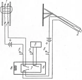
The device allows you to determine the rhythm, tempo of rowing, the duration of the carriage (rower) stopping in the forward position and at the end of the stroke, the time between the moment the carriage stops in the forward position and the moment the oar blade is immersed in the water, the speed of leg extension on the line (with a known length of the runners), approach speed (with a known length of runners).
The device diagram is as follows (Fig. 1): 1 - contact plates between the runners 2 — contact float on the oar blade 3 — time counter 4 - power supplies 5 - breakers 6 - tape drive 7 — relay-writers 8 - ink reservoir.
In the device, metal contact plates 2.5 cm high and 1 cm wide are installed between the runners at the level of their front and rear edges. When using the full length of the runners during sports rowing, the rower closes the contacts with the carriage axis for the entire time the carriage remains motionless. In carriages with paired wheels, where there is no transverse axis, a bare wire is stretched between the holders, the purpose of which is to close the contacts. A contact in the form of a float is installed on the oar blade. Once in the water, the contact closes.
Electric relays are used as writing devices, to which feathers made from syringe needles are attached. Ink for the pens comes from a common reservoir through flexible tubes. The recording can be made on paper tape.
A device for measuring the speed of sports rowing vessels.
The device allows both the athlete and the coach to continuously control the speed of the sports rowing vessel.
The device (Fig. 2, a) consists of a speed sensor, an electronic frequency meter and an indicator device. The speed sensor is a rotating drum 3, on the body of which twelve radially diverging spokes 2 are fixed around the circumference, ending with blades 1. A ball bearing 8 is mounted on the axis of the drum 9, which is pressed into the drum body 3. A perforated commutating ring 5 is glued to the protrusion in the drum body. A plate 7 is attached to the axis of the drum 9, on which a photodiode 6 and a light bulb 4 are mounted in such a way that the perforated commutating ring 5 is located between the photodiode window and the light bulb. The drum axis is screwed into the bracket 10, which is rigidly connected to the kayak body 11. The cover 12 protects the elements located in the drum body from water. The drum axis inside has a through hole for the output of wires that are connected to the photodiode and the light bulb.
The speed sensor is a rotating drum with radially placed spokes with blades at the ends. The drum is mounted on the bow of a sports rowing vessel using a special bracket (Fig. 2.6). The blades of the spokes are immersed in water, and the rotating drum is located above the water.
The rotation speed of the above drum by means of a photodiode, a light bulb and a special perforation ring is converted into successive electrical pulses with a frequency proportional to the speed of the vessel, measured by an electronic circuit and indicated by a dial gauge, the scale of which is calibrated directly in units of speed (up to 10 m/s). The device is located in front of the rower or coach sitting in the boat. High accuracy of speed measurement (2%) is ensured by the use of ball bearings on the axis of the rotating drum, as well as an electronic frequency meter.
The device is designed to take into account the athlete's load by counting the number of strokes performed in a certain time.
The schematic diagram of the device (Fig. 3) includes a closing contact 1, a carriage axis 2, a power source 3, a counter 4, a breaker 5. The closing contact provides for the closure of the electrical circuit only when the rower performs the wiring, i.e. when the carriage moves towards the bow kayaks or canoes. The contact lever is moved by the axis of the carriage or by a tensioned wire specially for this purpose in carriages with paired wheels in the absence of a long axis. When the carriage moves during preparation, the contact lever moves, but the contact does not complete the electrical circuit.
The closing contact is installed in the first third of the length of the skids (from the bow of the boat) in such a way as to take into account strokes performed with incomplete approach. The movement of the contact lever closes the electrical circuit, and a mechanical electric meter records the wiring. For convenience, it is advisable to place the electric meter, batteries and switch in a waterproof box.
Post Views: 121


