Sections: Technology
Goals and objectives of the lesson:
educational: show students how to use the rectangular projection method when making a drawing;
• the need to use three projection planes;
• create conditions for the formation of skills to project an object onto three projection planes;
developing: develop spatial concepts, spatial thinking, cognitive interest and creative abilities of students;
educating: responsible attitude towards drawing, to cultivate a culture of graphic work.
Methods and techniques of teaching: explanation, conversation, problem situations, research, exercises, frontal work with the class, creative work.
Material support: computers, presentation “Rectangular projection”, tasks, exercises, exercise cards, presentation for self-test.
Lesson type: lesson to consolidate knowledge.
Vocabulary work: horizontal plane, projection, projection, profile, research, project.
I. Organizational part.
State the topic and purpose of the lesson.
Let's carry out lesson-competition, for each task you will receive a certain number of points. Depending on the points scored, a grade for the lesson will be assigned.
II. Repetition of projection and its types.
Projection is the mental process of constructing images of objects on a plane.
Repetition is carried out using presentation.
1. Students are asked problematic situation. (Presentation 1)
Analyze the geometric shape of the part on the front projection and find this part among the visual images.
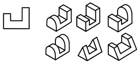
From this situation it is concluded that all 6 parts have the same frontal projection. This means that one projection does not always give a complete picture of the shape and design of the part.
- What is the way out of this situation? (Look at the part from the other side).
2. There was a need to use another projection plane. (Horizontal projection).
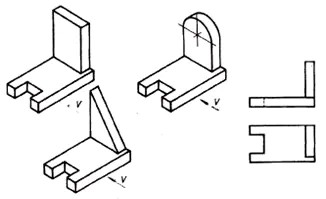
3. The need for a third projection arises when two projections are not enough to determine the shape of an object.
Sizing:
- on the frontal projection –
Conclusion: this means that in order to learn how to make drawings, you need to be able to project objects onto a plane.
Fill in the missing words in the definition text.
1. There are _______________ and ______________ projection.
2. If ______________ rays come out from one point, projection is called ______________.
3. If ______________ rays are directed parallel, projection is called _____________.
4. If ______________ rays are directed parallel to each other and at an angle of 90 ° to the projection plane, then the projection is called ______________.
5. A natural image of an object on a projection plane is obtained only with ______________ projection.
6. The projections are located relative to each other______________________________.
7. The founder of the rectangular projection method is _______________
Task 2. Research project
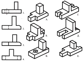
Match the main types indicated by numbers with the parts indicated by letters and write the answer in your notebook.
An exercise to review knowledge of geometric bodies.
Using the verbal description, find a visual image of the part.
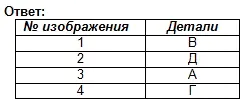
The base of the part has the shape of a rectangular parallelepiped, the smaller faces of which have grooves in the shape of a regular quadrangular prism. In the center of the upper face of the parallelepiped there is a truncated cone, along the axis of which there is a through cylindrical hole.
Answer: part No. 3 (1 point)
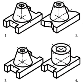
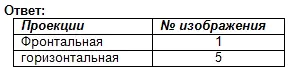
Find the correspondence between the technical drawings of the parts and their frontal projections (the direction of projection is marked with an arrow). Based on the scattered images of the drawing, make a drawing of each part, consisting of three images. Write your answer in the table (Fig. 129).
| Technical drawings | Frontal projection | Horizontal projection | Profile projection |
| A | 4 | 13 | 10 |
| B | 12 | 9 | 2 |
| IN | 14 | 5 | 1 |
| G | 6 | 15 | 8 |
| D | 11 | 3 | 7 |
III. Practical work.
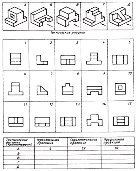
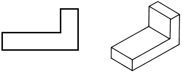
Task No. 1. Research project
Find the frontal and horizontal projections for this visual image. Write the answer in your notebook.
Assessment of work in the lesson. Self-test. (Presentation 2)
The points for grading the first part of the work are written on the board:
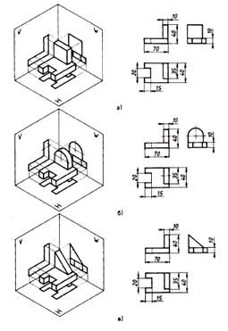
Task No. 2. Creative work and verification of its implementation
(creative project)
• Draw the frontal projection into your workbook.
• Draw a horizontal projection, changing the shape of the part in order to reduce its mass.
• If necessary, make changes to the frontal projection.
• To check the completion of the task, call one or two students to the board to explain their solution to the problem.
IV. Summing up the lesson.
1. Assessment of work in the lesson. (Checking the practical part of the work)
V. Homework assignment.
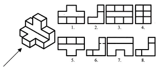
1. Research project.
Work according to the table: determine which drawing, designated by a number, corresponds to the drawing, designated by a letter.
A special case of parallel projection, in which the direction of projection is perpendicular to the projection plane, is called rectangular or orthogonal projection. The rectangular (orthogonal) projection of a point is the base of the perpendicular drawn from the point to the projection plane. The rectangular projection of points A and B is shown in Fig. 5.
To determine the position of a point in space from its parallel projections, it is necessary to have two parallel planes obtained in two directions of projection.
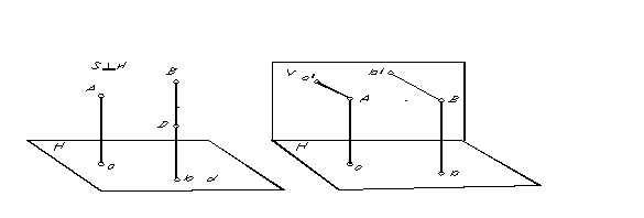 |
Because through a point, only one straight line perpendicular to the plane can be drawn, then, obviously, with orthogonal projection, in order to obtain two projections of one point, it is necessary to have two non-parallel projection planes (Fig. 6).
Orthographic projection has a number of advantages over central and parallel projection. These primarily include:
1. Simplicity of graphic constructions for determining orthogonal projections of points.
2. The ability, under certain conditions, to preserve the shape and size of the projected figure on projections.
The noted advantages have ensured the widespread use of orthogonal projection in technology, in particular, for the preparation of mechanical engineering drawings.
In mechanical engineering, in order to be able to judge from a drawing the shape and size of the objects depicted, when drawing up drawings, as a rule, they use not two, but several projection planes.
The position of a point in space, and therefore of any geometric figure, can be determined if any coordinate reference system is specified. Projection planes divide space into eight parts - octants. They are conventionally numbered with Roman numerals (Fig. 7).
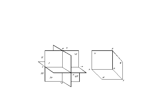
Projection planes divide space into eight parts - octants. They are conventionally numbered with Roman numerals (Fig. 7).
The most convenient for fixing the position of a geometric figure in space and identifying its shape from orthogonal projections is the Cartesian coordinate system, consisting of three mutually perpendicular projection planes. Due to the fact that descriptive geometry is designed to convey the results of its theoretical research for practical use, it is advisable to consider orthogonal projection also in a system of three projection planes.
For ease of projection, three mutually perpendicular planes are chosen as three projection planes (Fig. 8). One of them is usually placed horizontally - it is called horizontal projection plane, the other is vertical, parallel to the drawing plane, it is called frontal plane of projections and a third, perpendicular to the two existing ones - it is called profile plane of projections. These projection planes intersect along lines called projection axes.
We have adopted a right-handed system for arranging projection planes. In this case, the positive directions of the axes are considered: for the axis X (intersection of horizontal and frontal projection planes) – to the left of the origin, for the axis y (intersection of horizontal and profile projection planes) – towards the observer from the frontal projection plane, for the axis z (intersection of the frontal and profile planes of projections) – upward from the horizontal plane of projections, the opposite directions of the axes are considered negative.
The projection of a point is the base of the perpendicular drawn from the point onto the corresponding projection plane. Horizontal projection points are the rectangular projection of a point on a horizontal projection plane, frontal projection – respectively on the frontal plane of projections and profile – on the profile plane of projections.
It is inconvenient to use this spatial layout to depict orthogonal projections of geometric figures due to its bulkiness, and also due to the fact that on individual ones (horizontal and profile) the shape and size of the projected figure are distorted. Therefore, instead of depicting a spatial layout in a drawing, they use a complex drawing (Monge diagram) composed of three interconnected orthogonal projections of a geometric figure.
The transformation of the spatial layout into diagrams is carried out by combining the horizontal and profile projection planes with the frontal projection plane (Fig. 7).
Since the planes have no boundaries, in the combined position (on the diagram) the boundaries of the planes are not shown, there is no need to leave inscriptions indicating the position of the projection planes (Fig. 10).
Having switched to the diagram, spatial clarity was lost. The diagram gives more - accuracy and ease of measurement of images, with simplicity of construction. However, to imagine a spatial picture requires the work of imagination.
Didn't find what you were looking for? Use the search:
Best sayings: For a student, the most important thing is not to pass the exam, but to remember about it in time. 9744 — | 7364 - or read all.
Projection drawing (basics of descriptive geometry)
Projection method
Rectangular projection method
If the projecting rays make a right angle with the projection plane, then such projections are called rectangular.
Rectangular projections are also called orthogonal. The word "orthogonal" comes from the Greek words "ortos" - straight and "gonia" - angle.
Drawings in the system of rectangular projections give a complete picture of the shape and size of the object. They are easier to perform than axonometric projections.
What do you need to know to successfully complete drawings?
Any object that has flat surfaces is limited by vertices, edges and faces (Fig. 108). Therefore, in order to learn how to depict various objects in drawings, you need to know how vertices (points), edges (segments of straight lines) and edges of objects (parts of a plane) are depicted in rectangular projections.
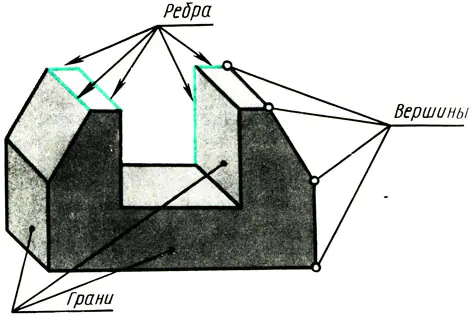
Rice. 108. Premsch as a set of points, write. Vertices of planes
Let's do a simple experiment. Let's see how a flat object and a hundred elements are depicted in different positions.
Let us take the wall opposite the window as the projection plane. Let it out the window perpendicular Rays of light fall on the wall - projecting rays. Place a sheet of thick ABCD paper in front of the wall (parallel to it) (Fig. 109, a). A shadow is formed on the wall, equivalent to the projection of the object. What are its dimensions? In this case, the projection a’b’c’d’ corresponds in shape and size to the object of projection - the sheet
ABCD. The projection method is rectangular, since the projecting rays are perpendicular to the projection plane.
How will the projection change if the depicted object is rotated, for example, around its height - edge AD (Fig. 109, b)?
When turning, the shadow will shrink in width (lines a’b’ and c’d’ in Fig. 109, b become shorter). Continuing to rotate the sheet of paper, we note that in a position perpendicular to the wall, the image of the sheet will turn into a line (Fig. 109, c), but the height of the object remains constant, i.e. lines a'd' and b'c' along the length are not distorted.
Now let’s formulate conclusions about what shape and size images a flat object has in rectangular projections, differently located in relation to the projection plane:
a) a flat figure parallel to the projection plane is depicted on it in natural size (Fig. 109, a);
b) a flat figure, inclined to the projection plane, is depicted on it with a distortion of dimensions (Fig. 109, b);
c) a flat figure perpendicular to the projection plane is depicted on it in the form of a straight line segment (Fig. 109, c).
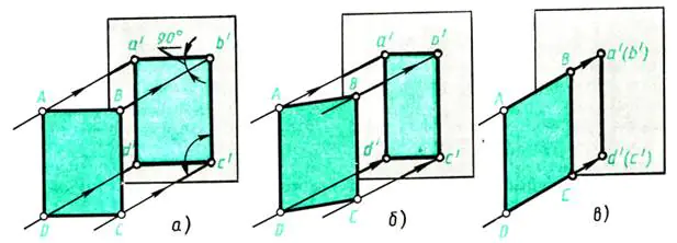
Rice. 109. Projecting a flat figure
These findings relate to the depiction of the edges of objects.
How are the edges of objects, i.e. lines, depicted in rectangular projections?
Let's repeat the experiment with rotating a flat object, observe how its edges, i.e. lines, are projected, and draw conclusions:
a) a straight line segment parallel to the projection plane is depicted on it in natural size (compare the height of the object AD and BC in Fig. 109, a, b, c with its projections a'd' and b'c, and the width of the object AB and CD with its projections a'b' and c'd' in Fig. 109, a);
b) a straight segment inclined to the projection plane is depicted on it with a distortion in length (compare the width of the object AB and CD in Fig. 109, b with its projections a’b’ and c’d’);
c) a straight line segment perpendicular to the projection plane is depicted by a point on it (see in Fig. 109, across the width of the object - lines AB and CD, perpendicular to the projection plane).
The projection of a point is the base of a perpendicular lowered from a given point in space onto the projection plane (see points a’, b’, c’, d’ - projections of points A, B, C, D).
Let us agree to denote points in space by capital letters A, B, C, D, etc., and projections of points by the corresponding lowercase letters i, b, c, d, etc.
Of the two points coinciding in the drawing (Fig. 109, c), one is an image of a visible vertex, and the other is an invisible (closed) one. The designation of projections of invisible vertices is taken in brackets.
